DRDO Technology e-Bulletin
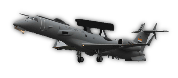
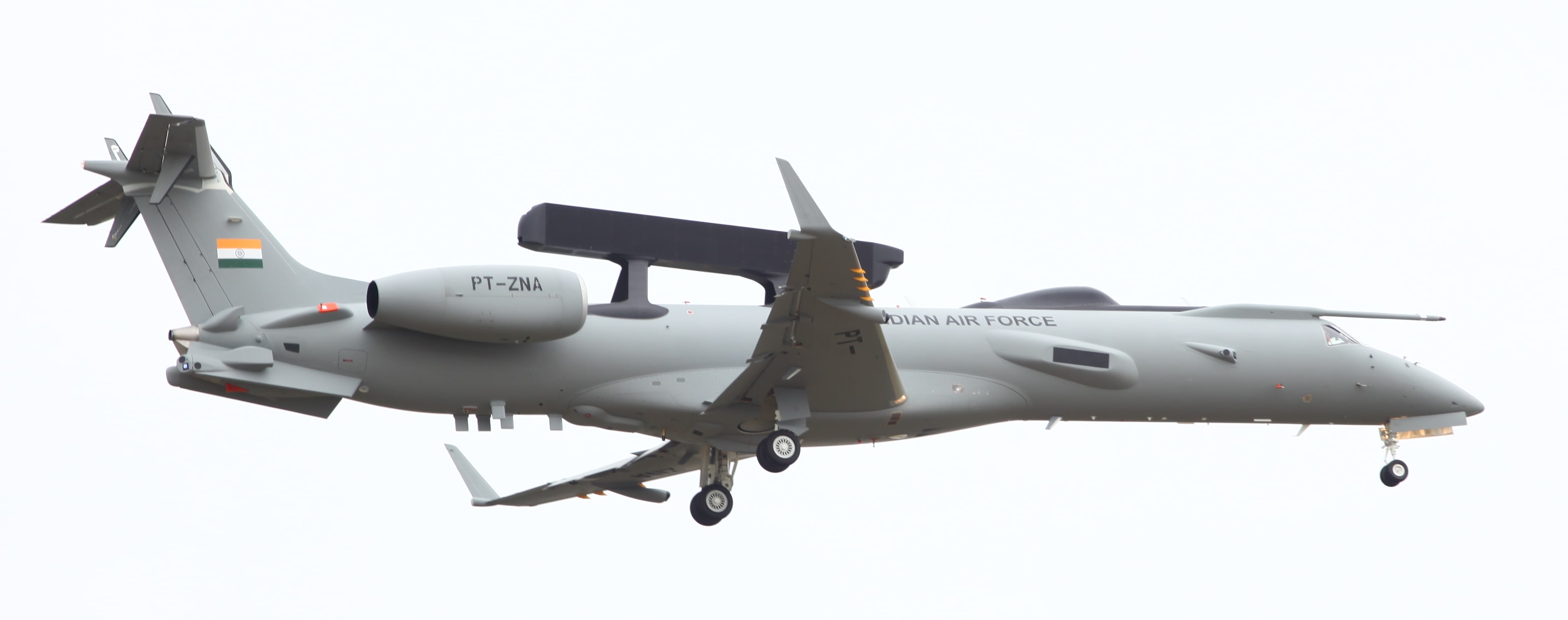
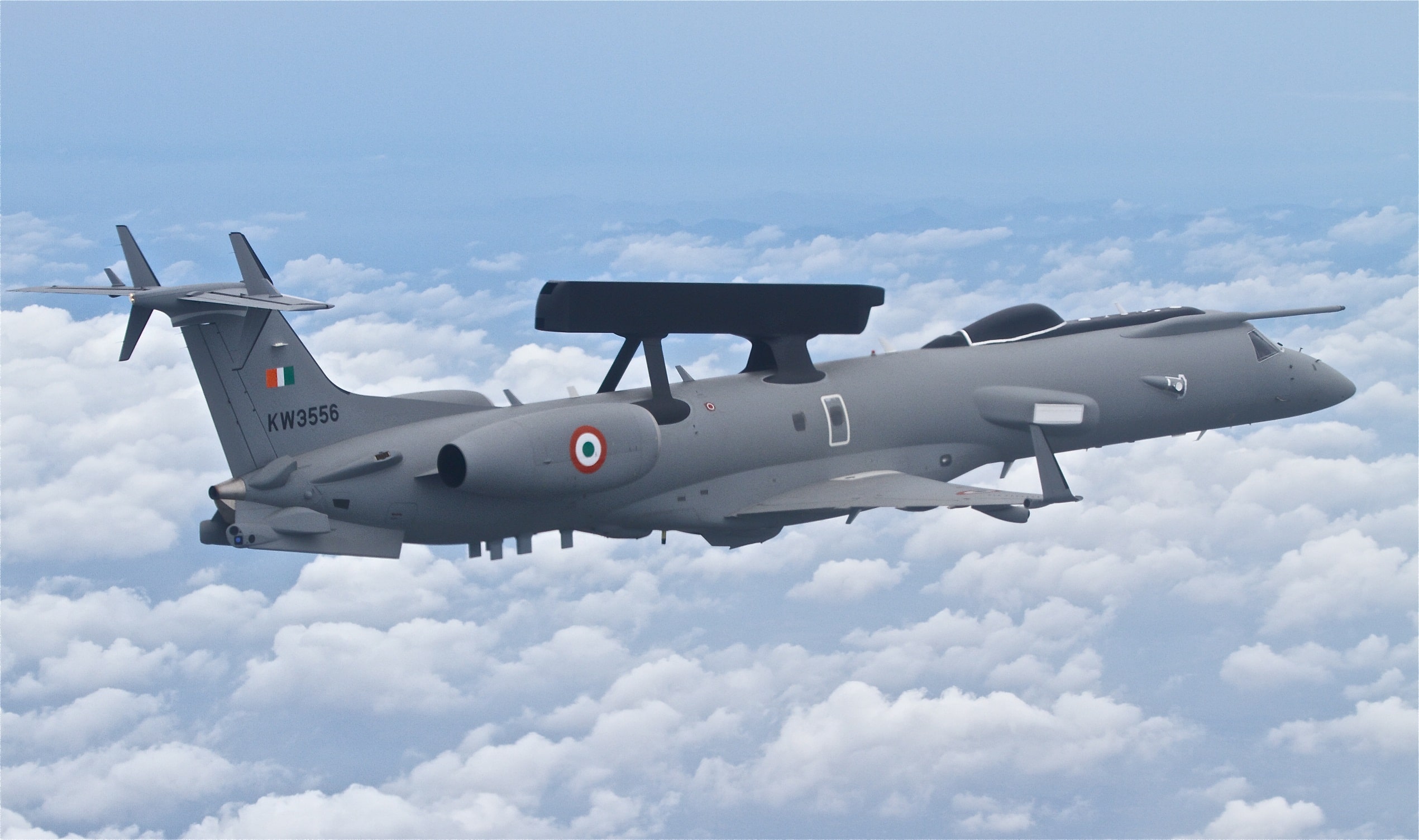
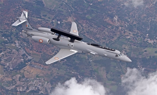
NETRA : THE INDIGENEOUS AIRBORNE EARLY WARNING & CONTROL SYSTEM
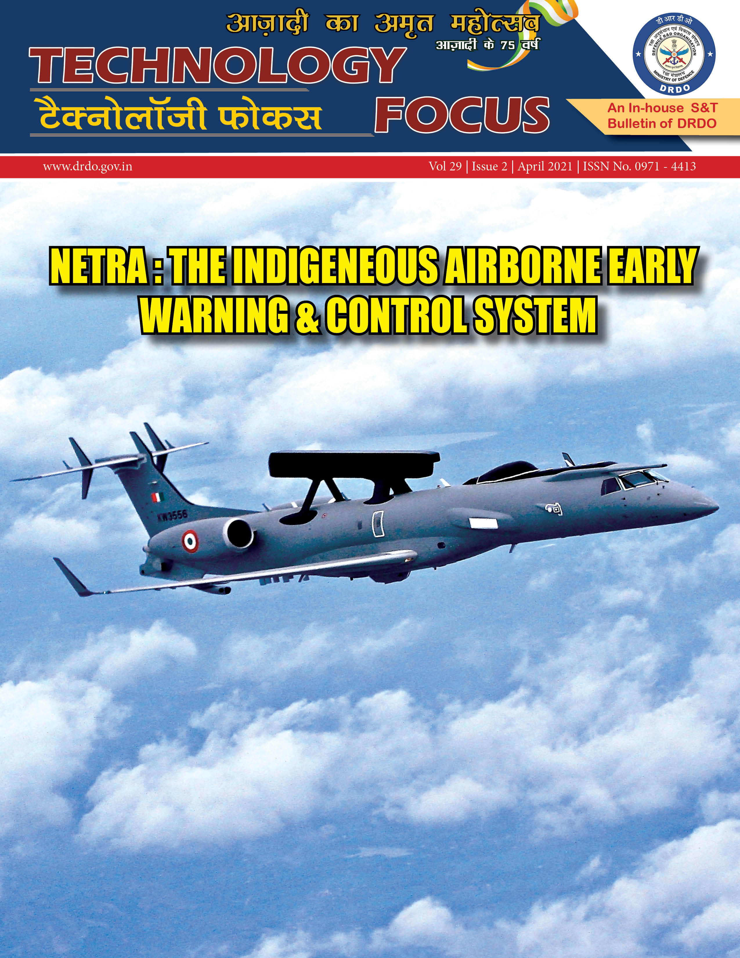
 On 14th February 2017, in front of international gathering at Aero India Exhibition and in a short and sweet but unforgettable ceremony, for CABS & DRDO, the first indigenously developed Airborne Early Warning and Control System was formally handed over to IAF. Chairman DRDO, symbolically handed over the keys of the aircraft to Hon’ble Defence Minister late Shri Manohar Parrikar and he in turn handed over the keys and certificate to the then Chief of Air Staff.
It was one of the most sombre moments in the history of DRDO & CABS. The Country emerged as one of the few nations to have achieved this feat. The journey to this achievement was arduous and eventful. From its inception, till date, CABS has had roller coaster ride. Being created as ASWAC (Airborne Surveillance, Warning and Control) centre in the year 1985, to study the feasibility of developing Airborne Warning and Control System (AWACS), in the country, it translated itself into a Centre for Airborne Systems (CABS) with a charter to design and develop the AWACS systems in 1991.
CABS then took up a challenge to convert an Avro Aircraft into a mini AWACS namely Airborne Surveillance Platform (ASP). The endeavour to develop this system was successful and critical systems such as primary radar and data links were developed and demonstrated. However, the experiment ended in an accident, which plunged CABS into despair.
The resurrection of CABS happened when IAF started the procurement of the AWACS system from foreign sources. In parallel, it also projected a requirement for a system on an executive jet class of aircraft and preferred it to be developed by DRDO. A joint team then evolved broad operational requirements. Based on this, DRDO then submitted a draft note for approval to Government in August 2004.
The approval of the programme for development of indigenous AEW&C by CCS was cleared within a week of its submission. The then Hon’ble RM announced in public that India is venturing into development of AEW&C system indigenously.
The AEW&C Programme went through several moments of excitement and despairs, ups and downs, all of them worthy of a thriller book.
In short, the design teams at CABS, DRDO work centres at LRDE, DLRL, DEAL, DARE, ably supported by IAF Project Team at CABS, CEMILAC, DGAQA, DRDO HQ, IAF HQ and Squadrons, ASTE etc., worked closely to catapult the country into the league of nations with Airborne Surveillance system development capability.
On 26th January 2017, the AEW&C was flown for first time in the Republic Day Fly Past. The call sign for the AEW&C was NETRA. The announcer, announced its flight as Indian AEW&C NETRA as it flew past the main podium. This name became synonymous with the system since then.
Netra has proved its mettle in actual operations in Balakot and two Netra Systems have merged as one of the mainstay of the Airborne Surveillance Systems of the IAF.
Today, CABS is poised to take a large leap in sustaining the effort of the AEW&C to deliver several airborne surveillance systems not only to IAF but also to other agencies such as Indian Coast Guard, NTRO, etc.
Personally, I have been fortunate to be part of this thrilling journey during the second coming of CABS, and also blessed to be Director, under whose watch the delivery of these systems took place.
I would like to dedicate this issue of Technology Focus on CABS and its achievement to all those who have contributed to the journey of CABS and its success.
MS Easwaran
Distinguished Scientist
Director (CABS)
The development of an indigenous Airborne Early Warning and Control System (AEW&C) was taken up by DRDO & IAF in 2004. The mandate required development of three AEW&C systems comprising of Active Electronically Scanned Antenna based Primary Radar (PR), Identification Friend or Foe (IFF), an ELINT and SIGINT system all hosted on an executive jet platform namely the Embraer-145. The system was envisaged to have full net centric capability through multiple LOS and Satellite Communication Data links, on-board Mission Computer, which enables the operator to carry out the information fusion, mission control, and reconfigurable operator consoles for the operator to interact with the system and exploit the system capabilities in tune with the operational environment. The dream was realised on 14 February 2017 with the handing over of the system to the Indian Air Force.
Currently two AEW&C systems named Netra, are being used extensively by the Indian Air Force for various operations.
This issue of Technology Focus discusses various system, sub-systems and the technologies incorporated in the Netra and various technical facilities established at CABS to realise the mission AEW&C System.
The AEW&C system configuration
The AEW&C is a system of systems force multiplier coveted by every military force of the world. Any modern AEW&C/ AWACS systems are madeup of a suite of several sensors, communications, and computing systems that make them truly C4ISR systems.
The primary sensor of any airborne system is the Primary Radar, mainly due to its ability to detect moving targets at long distances, in all weather conditions.
The Indian AEW&C country’s first ever fully active array primary radar system (PR) system is fully indigenous, in the sense that complete system including its electronics, antenna array etc. have been designed and manufactured by DRDO in the country. The critical electronics such as the Transmit Receive module etc. have been designed, developed by DRDO and productionised by an industry partner.
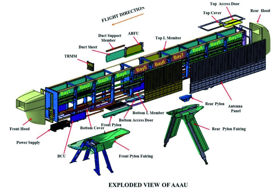
Active Antenna Array Unit (AAAU) is a major as well as critical component of the AEW&C system and has been indigenously developed state-of-the-art technology for the first time in India. The external shape of AAAU is made considering aerodynamic loads and drag. Internal design is made to optimize the cable routing, for accommodation of front end electronics of primary & secondary surveillance radars and cooling of them. The fool proof design of AAAU caters for antenna structure, thermal, microwave electronics & digital electronics.
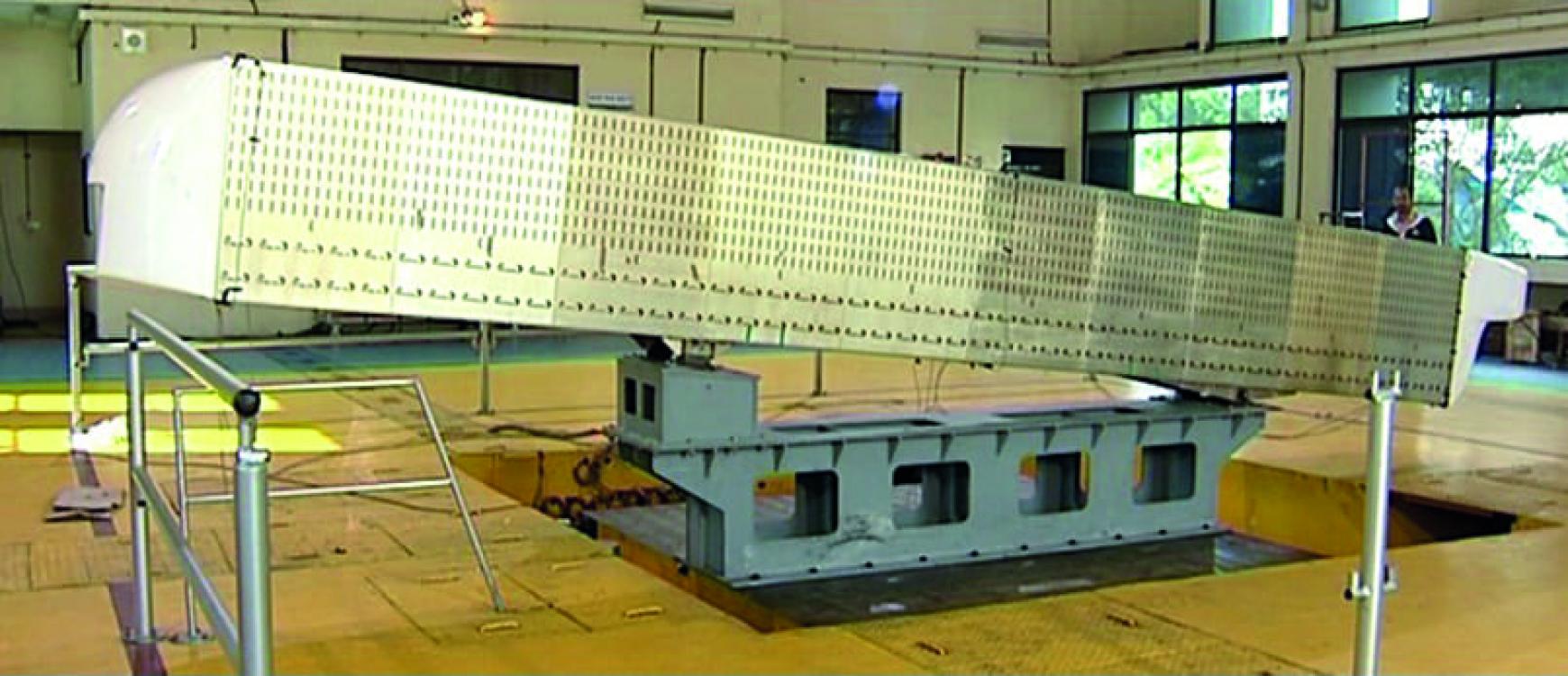
The AAAU is mounted on dorsal side of the aircraft fuselage using four pylons. Being an external structure of an aircraft with the dimensions of 8.2m X 0.9m X 0.5m, it qualified stringent airworthiness requirements. AAAU structure is designed for aerodynamic loads, inertia loads and aero-elastic requirements. The mechanical design of AAAU is designed considering easy accessibility for various electronic components (LRUs) inside the AAAU.
Optimal RAM air cooling design of AAAU provides effective and uniform cooling of the LRUs. The front hood and antenna panels were structurally optimized, tested and certified for bird impact requirements specified in Federal Aviation Regulation (FAR – 25). Wind tunnel tests and CFD studies were conducted for the AAAU to optimize the aerodynamic shape of front and rear hood and to estimate the internal and external aerodynamic loads. Structural tests such as Modal Analysis Test (MAT), Static Strength Test (SST) and Ground Vibration Test (GVT) were conducted and validated with Finite Element Analysis.
The electronics in the Primary Radar of AEW&C is a modern stateof-the-art indigenously designed early warning radar with active phased array technology as its radiating interface. The radar offers multifunction, multi-mode capability with highly agile beam steering and electronic beam stabilization by the array.
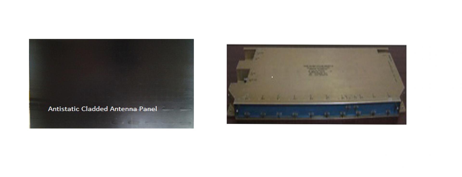
Radiating interface, the major subsystem of the PR Active Electronically microwave & electrical technologies. Its sophisticated electrical power distribution system comprises enough safety measures. The performance of the array is maintained by in-situ calibration system. Critical building block that supports all functional requirements of the radar and serves as heart of the AAAU system are TRMMs. The TRMM’s also have RF and digital manifolds to accommodate the size and weight due to its unique design. CABS hold the patent on the TRMM design along with M/s AMPL (production house). The unique design of Scanned Array (AESA), is first of its kind. CABS not only achieved the design of RF manifolds of the AAAU system but also built the structure of AAAU to support airborne requirements. To obtain higher sensitivity, the AAAU is designed with high power transmit capability and also achieved ultra-low side lobe level in the receive mode.
The AAAU array has been developed with amalgamation of analog and digital electronics, integrated antenna aperture for both primary and secondary surveillance system along with cladded radome has reduced the weight and volume constraints.
This uniqueness has also helped in bringing out the microwave losses thus making it a win-win from both structural and electronics aspects. With the aid of several stages of RF distributer and combiner networks single RF signal input is fed to all elements of planar array. The received signals from all elements are combined by TR modules and stages of RF combiners.
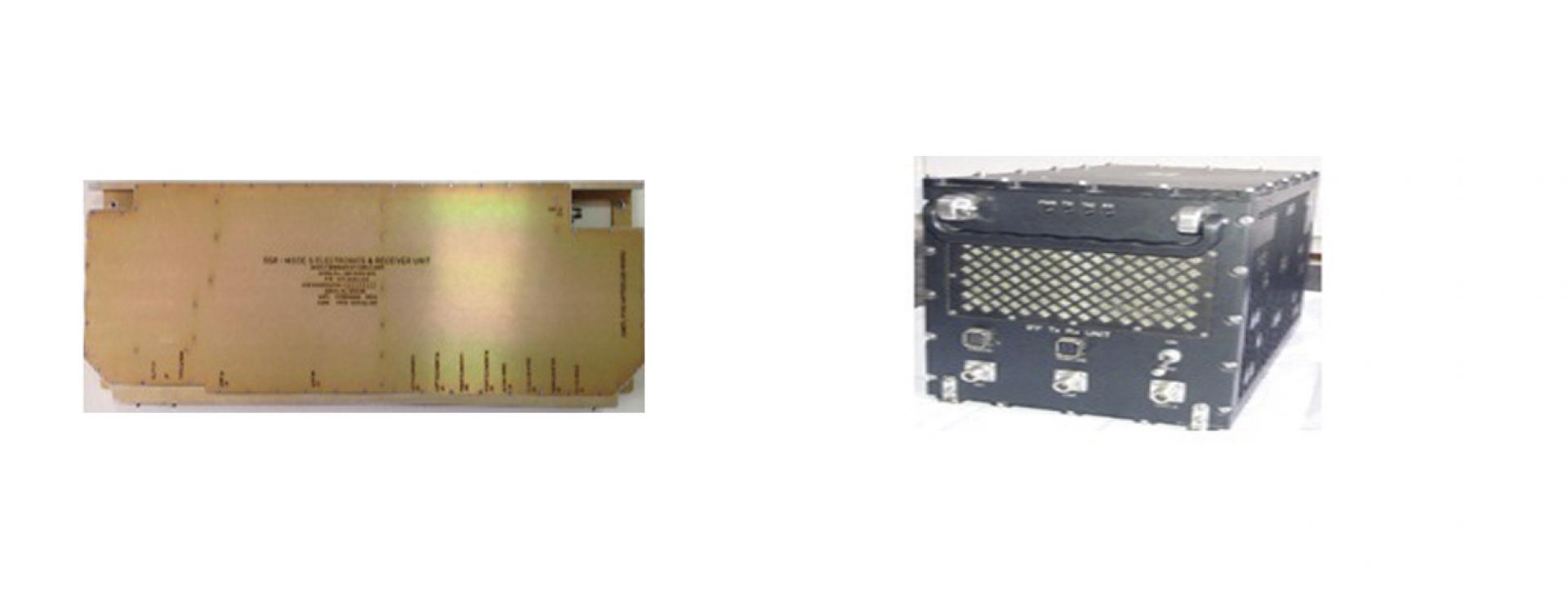
To achieve the command & control of installed LRU’s of AAAU system, a controller has been devised with required hardware and software. The unit accepts the control and commands information from central unit/IFF SP/MSC through specific interfaces and distributes the same to AAAU LRU’s. The airborne radar surpassed multitudes of challenges involved. The system has been regularly operated by the users.
Secondary Surveillance Radar (SSR) is another important sensor in AEW&C system used for detecting targets, identification as a friend or foe while working in tandem with Primary Radar (PR). This information is very vital in the wartime and is also useful to form database during peace time surveillance.
SSR system also called Identification Friend or Foe (IFF) system in military terminology comprises of an interrogator fitted with the main radar system on airborne platform and a transponder fitted on target aircraft. It operates as per the recommendations of the International Civil Aviation Organisation (ICAO) and STANAG 4193. The interrogator transmits pulsed signal in a particular mode of interrogation in a specified direction. Aircraft fitted with compatible transponder receives the interrogation signal and replies back Technology Focus in the form of another coded signal to the interrogator for processing and identification. The reply provides additional target details such as height, range and azimuth, and target status like communication failure, emergency and hijack. Mode 4 is an encrypted mode of operation that enhances its capability to be secured, jam resistant and resistant to spoofing. Operation in Mode S (level 2) gives capability of selective addressing and data link capability, which are very critical in dense air traffic.
Based on the requirements of the user and platform constraint, the high power airborne IFF MK XII(S) interrogator has been developed for the AEW&C programme with a range of more than 375 km using modular approach. It comprises of Electronically Scanned Antenna Array (ESAA), solid-state transmitter, dual channel monopulse receiver and signal processor. All the LRUs of IFF system have been qualified as per the MIL STD 810E/461E/704D and certified for airworthiness by DGAQA/CEMILAC, and has been thoroughly tested in System Test & Integration Rig.
More than 700 user evaluations were carried out by AFPT and ASTE including Large Fleet Engagement (LFE) sorties at various places in India.
Formal ATP has been carried out by the IAF task team. Two IFF systems with adequate spare has been inducted into the IAF.
The detection by the sensors brings out certain attributes of the object in space. Multi Sensor Data Fusion (MSDF) fuses all data (geometric, kinematics, attributes) pertaining to one target object into one single identified & classified track and enables a better situation awareness in order to have faster and more reliable decisions and significantly enhancing mission effectiveness. This data fusion process is supported and controlled in accordance with the actual task and mission. The ultimate goal of MSDF is a crucial contribution towards information superiority, which results in an identified & classified track with optimized accuracy, stability, continuity and reliability for each target object.
The objectives of Mission Data Processor of AEW&C are:
◊ Generation of accurate system tracks
◊ Identification and Classification of System tracks
◊ Automatic evaluation of threats for the system tracks
The Data fusion model for AEW&C has been derived from the standard JDL model. It consists of low-level and high-level processes. The lowlevel process includes target detection, classification, fusion, and tracking. High-level process encompasses situation and threat assessment.
The MSDF module fuses the sensors state vectors and covariances using a fusion formula. The identification module identifies the track as friend, hostile, neutral, etc. and also classifies the track as fighter, transport, helicopter, etc. The processing is carried out considering various databases (FPL, IFF mode/code table, etc). The threat assessment module evaluates the threat for the identified track against the vulnerable areas and points. The module generates appropriate alerts (trespass and approach) and aids operator in quick decision making These tasks are accomplished using fuzzy logic and voting techniques to arrive at the rationale for carrying out the identification, classification and threat assessment of the targets.
The AEW&C system is a command and control station in air for control and directing the fighters during large fleet engagements and carry the battle management functions or alternatively act like a network centric node in the Integrated Air Command and Control of the IAF and interfaces the data over the datalinks to contribute for the air situation picture of the Integrated Command and Control Station.
This Intercept Control and Battle Management (IC&BM) acts as a decision aid to the fighter controller to attain and sustain air superiority over a contested air space. It aids the fighter controller in threat assessment of airborne targets, to take tactical actions, to neutralize these targets, to guide fighters along the route for offensive strike missions and to recover aircraft to an airbase. The IC&BM module also depicts the survivability and vulnerability of interceptors against the threats. The Intercept Control computes a set of interception solutions to present to the operator to aid in assigning specific fighter(s) against a designated threat. It generates commands to the fighters based on guidance algorithms considering the fighter performance and various tactical inputs for interception, guidance and recovery operations. The design of the module includes consideration of target and interceptor capabilities including that of the weapons onboard, aircraft performance both in vertical and horizontal profile. The guidance algorithms of intercept control aid the operator to:
◊ Assess threat against the air and ground assets and plan course of action
◊ Attain and sustain air superiority over contested air space
◊ Provide intercept solution for achieving a successful weapon launch
◊ Avoid interceptor’s entry into enemy’s weapon launch range
◊ Arrive at the kill point with an advantage either in position or in energy
◊ Optimize fuel consumption during interception
◊ Plan Offensive Strike Missions
◊ Recover the aircraft after the interception/guidance mission
◊ Plan coordinated attacks to increase the kill probability
The IC&BM is composed of five major functionalities i.e., Advanced Threat Evaluation (ATE), Weapon Assignment, Intercept Control (IC), Battle management, Guidance and Recovery.
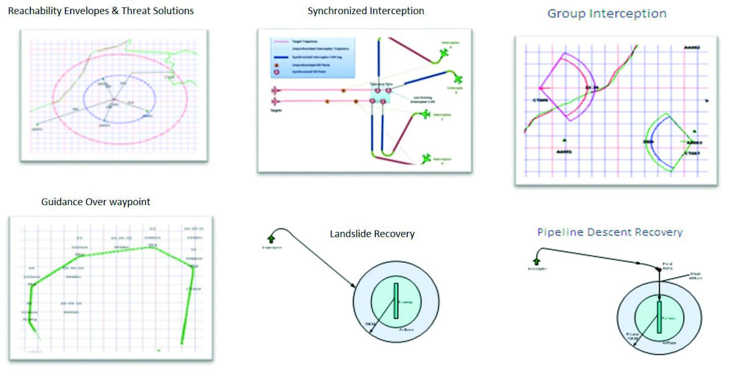
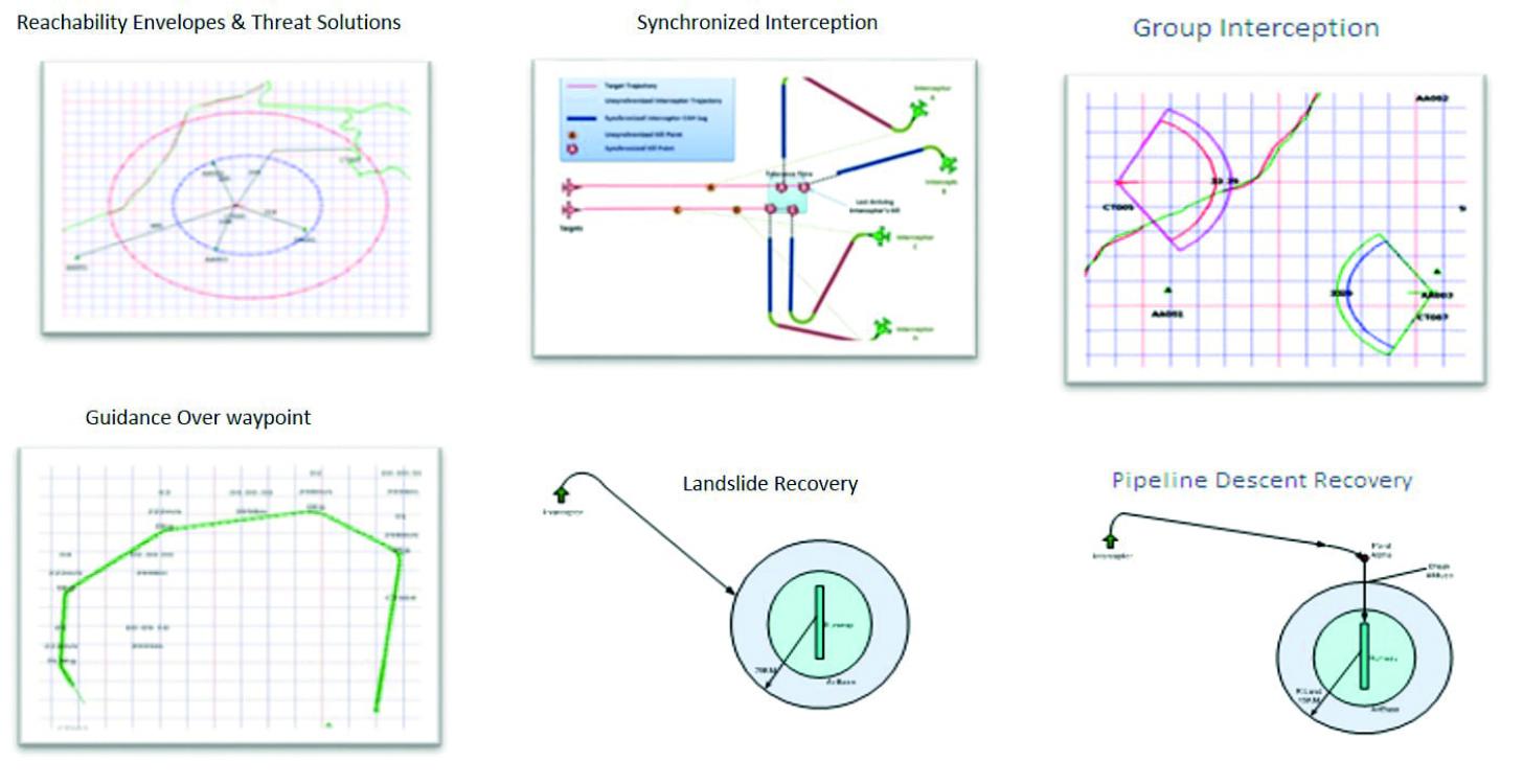
ATE carries out the threat assessment of a target against valuable ground as well as air assets considering the reachability envelope approach, type of aircraft, intention of target and the time the target will take to reach the asset. The ATE evaluates the threat posed by an operator specified track on the assets. The assets can either be specified by the operator or selected by the system based on configuration parameters decided during the design. The threat level generated by the ATE is further displayed to the operator to take an appropriate action.
The ATE also facilitates generation of the Threat Evaluation Solution using the guidance algorithm, i.e., collision course, which shows the shortest path that the threatening track will take to reach the asset. The degree of threat and the threat level is computed based on the capability of the threat (time to strike considering aircraft performance), the intention of the threat and the threat hostility index.
Weapon Assignment functionality of IC&BM generate intercept solutions for designated interceptortarget pair based on the input parameters selected/provided by the operator. The target and interceptor are manually selected by the operator. The proposed solution is generated considering the kinematics of interceptor and target, aircraft performance of the interceptor, the weapon on-board the interceptor and the tactics.
The functionality aids the operator to take decision by providing multiple proposed intercept solutions against the same target simultaneously. Based on the proposed intercept solutions the operator gets a clear picture of the interception trajectories and time required for intercepting the target. The IM functionality of IC facilitates the operator to activate the proposed interception solutions for an interceptor(s) to achieve the kill at the earliest.
Battle Management functionality of IC includes group interception and synchronized interception. In group interception, the leader interceptor is selected and the member interceptors are guided towards the leader so as to attain their position in a pre-defined group with respect to the leader. The group interception solution is evaluated using the collision course method based on the inputs i.e. structure type, structure size, tolerance period, etc. Dynamic threat evaluation functionality of IC evaluates the possibility of one track coming in the weapon envelope of another track by processing the weapon envelope of each aircraft to generate alerts accordingly. The generated alerts and the envelopes are presented to the operator to take evasive action in case the friendly aircraft is about to come within the weapon envelope of the enemy aircraft.
Guidance functionality of the IC&BM is mainly used for offensive missions wherein the fighter is guided towards a target through a pre-defined route. The guidance solution depicts the trajectory and the expected time of arrival at each waypoint.
Recovery functionality of IC is carried out at the recovery phase, i.e., after combat phase. This functionality enables recovery of the interceptor back to its recovery airbase on operator initiation.
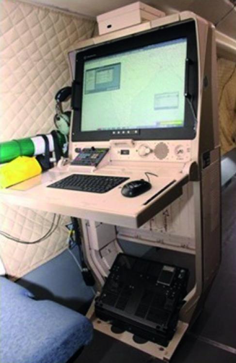
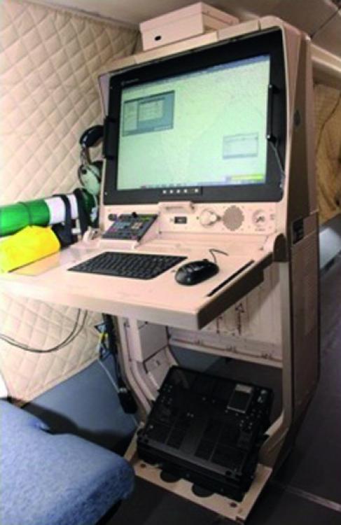
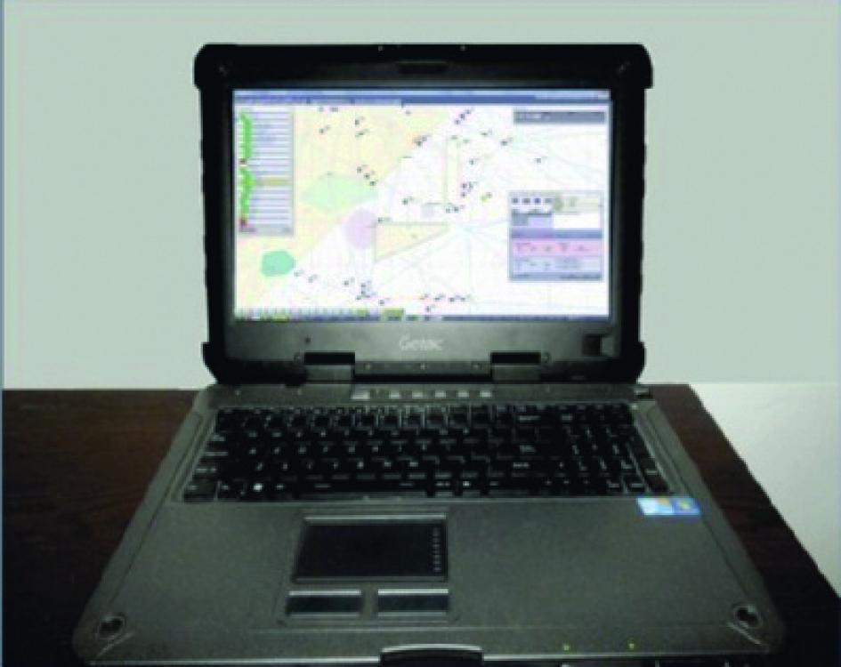
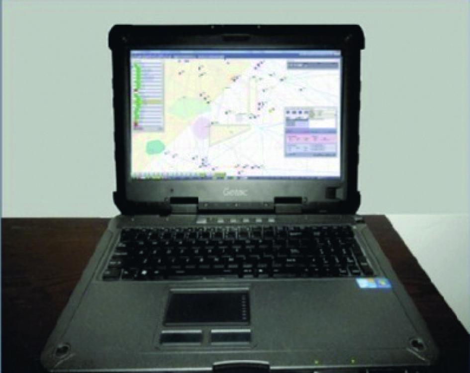
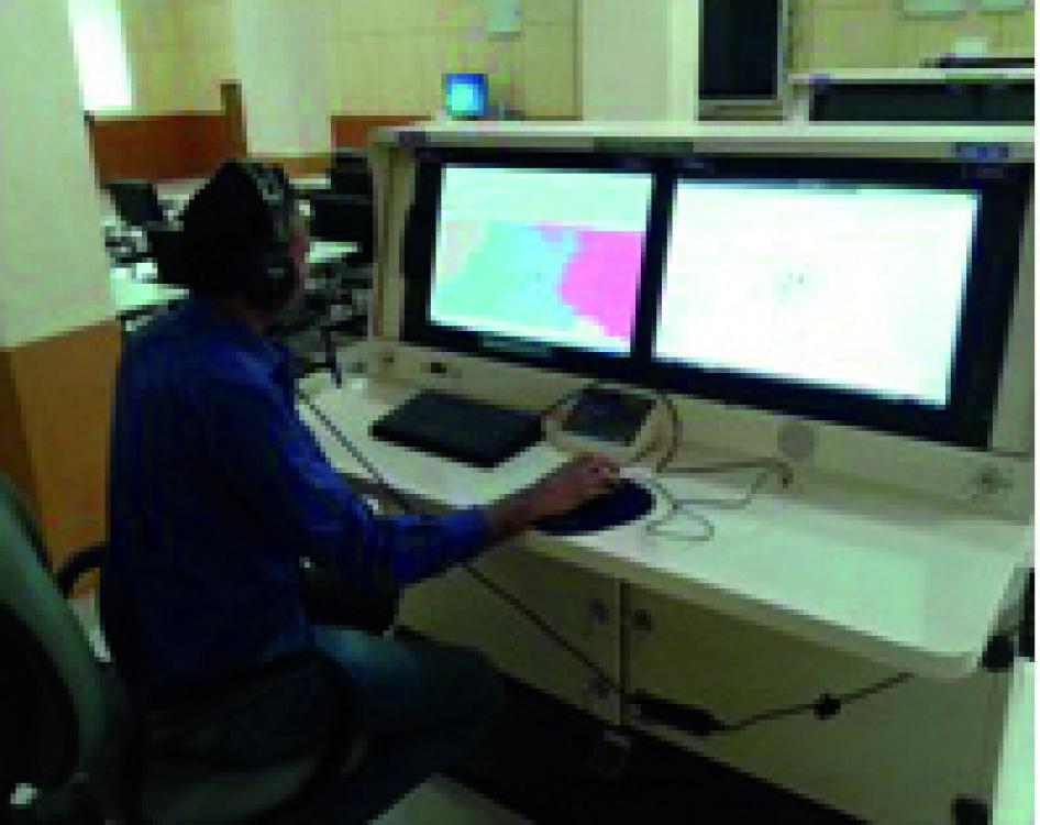
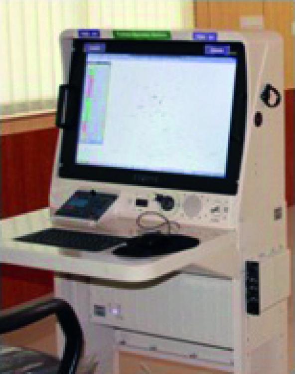
The face of the AEW&C system through which the operators interact with the Mission Systems onboard is the Operator Work Station (OWS). CABS OWS developed in-house to provide the operator a real-time display of the integrated tactical air situation picture on a powerful and ergonomically designed HMI, which enables the operators gain a better situational awareness of the region under surveillance. There are rugged and lightweight five front facing airborne qualified operator consoles onboard.
Each OWS receives tracks, plots and emitter data from radar, IFF, ESM & CSM systems via the Mission System Controller (MSC) and provides an Air Situation Picture (ASP) to the operator. The OWS has a lightweight map engine capable of rendering both vector maps and raster maps. It supports multiple projection and coordinate systems and allows the operator to select the map layers such as coast lines, roads, and towns of his choice. The data received through the sensors are presented to the operator in different formats like symbols, textual windows, histograms, spectrum display, waterfall display etc, aiding in operations. An operator deals with complex and large amounts of data and OWS provides better data organization, processing and distribution of actionable information, improving efficiency and reducing the reaction time.
The OWS provides capability of initiating interception of a hostile target, reception of the interceptor guidance solutions and commands from the MSC, facility for manual correlation of radar track data with ESM/CSM emitter data. It provides operational control facilities to all the AEW&C systems through keyboard and mouse. Emergency/Warning indications are provided via onscreen messages & audio beeps. The OWS receives the health information periodically from all sub-systems, via MSC and provides a comprehensive health status display of the systems onboard. Capability to view and monitor different areas of surveillance are provided through multiple Picture-in-Picture windows. Various tools help de-clutter the workspace and manage more electronic data.
The five airborne qualified operator consoles comprise a 24” rugged LCD display integrated with a chassis housing multiple Intel-based Single Board Computer (SBC). The OWS has an audio interface through a control panel that enables the operator to access all the communication channels with press of a button while simultaneously operating the display along with headset and integrated speaker. A foldable desk with a keyboard & mouse, knob-tilting arrangement for the monitor, reading area with transparent glass, light for reading during low visibility, pedal control with PTT switch are some other features of the consoles.
The operator consoles are designed as per the MIL-STD1472F ergonomics. The design also considered, in consultation with the Indian Institute of Aviation Medicine, the ergonomics of operators. The seats are adjustable according to the height and can be tilted. A twolevel adjustable foot rest facilitates operators with different heights to carry out operations.
Each of the five operator consoles are software reconfigurable to work in one of the six modes according to the role of the operator who is operating on it. The 6 modes of operation are: Air Situation Picture (ASP) / Command & Control (C2) i.e., ASP/ C2; ASP/C2 + CSM; ASP/C2 + ESM; Global Air Situation Picture (GASP) Reconstruction & Playback; Image & Voice Playback(IVPB) and Onboard Training mode.
Facility is available to the operator to switch modes as per operational requirements. This allows the operator to view the information according to his requirement. The ESM and CSM operators have been provided GUIs that provide more information on their respective sensors in the ESM and CSM mode.
The data along with audio and video of each OWS is recorded and stored for analysis and playback. The GASP mode provides a reconstruction of the entire mission and allows the operator to interact with the display. The IVPB mode provides an audio video replay of the mission. The operators can playback at various speeds, pause and bookmark various entities of interest. The two different playback modes provide the operator with unique and enhanced tools to analyze data post mission. It helps them to further fine-tune their strategy and to suggest further improvements to system. The requirement to meet the audio video recording of the mission is catered to by a recording unit.
The Onboard Training Mode provides the operators facility to designate instructor and trainee consoles for providing training onboard during the mission. Along with the onboard training mode, several training sessions have been provided by the CABS team to the command and control operators to train them on the system.
OWS has been inducted in two AEW&C systems, at 200 Sqn of the IAF. Close to 1,000 hours of development flight testing had been carried out. Air Force has also carried out extensive evaluation of the system under realistic operational conditions and through simulated exercises at various bases including large-fleet engagement exercises.
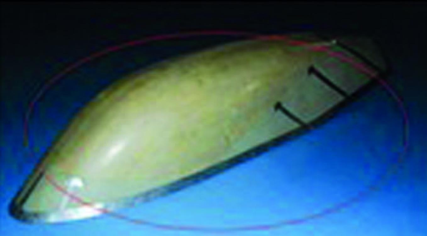
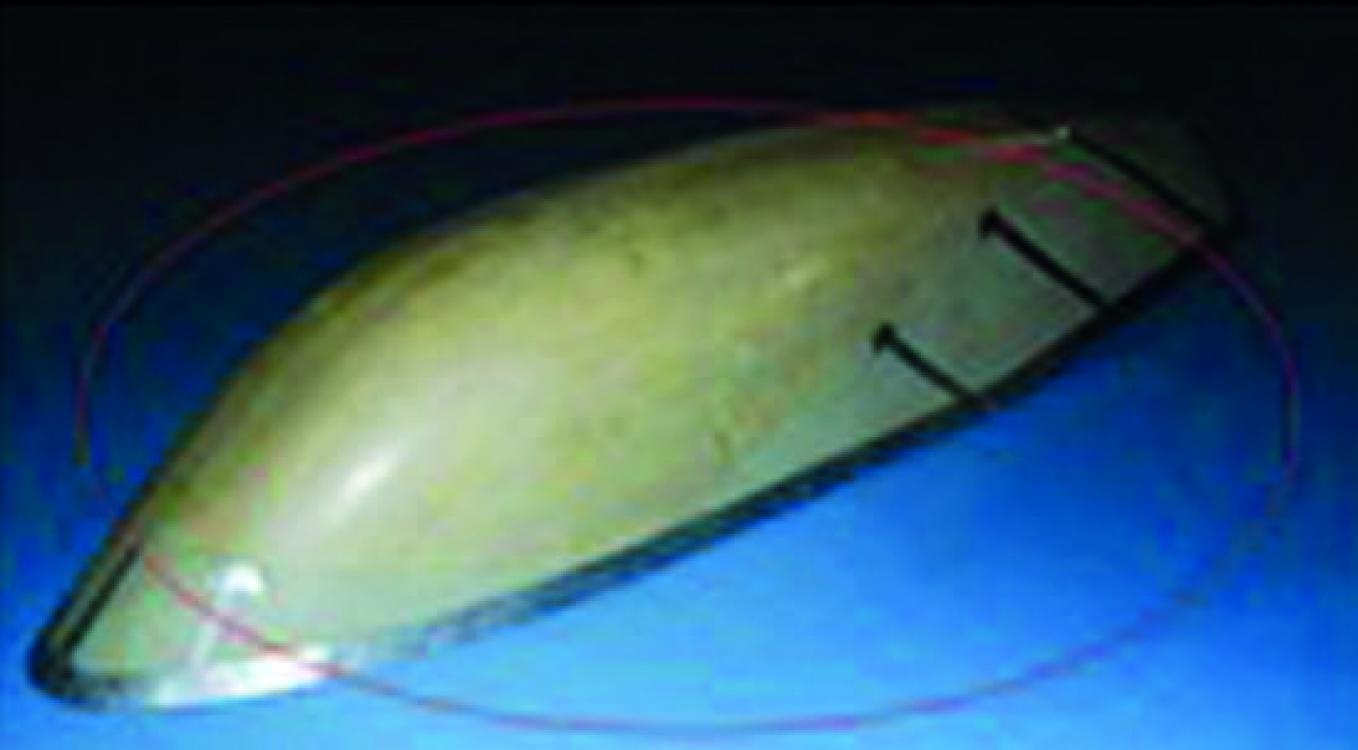
Satellite Communication (SATCOM) is one of the sub-systems of AEW&C system and is mounted on the top of fuselage of EMB145I aircraft. A radome protects the antenna from environmental effects in addition to transmit and receive electro magnetic radiations. This radome has been designed and developed by CABS and manufactured by a private partner.
Radome meets MIL-R-7705B specifications. Electro-magnetic (EM) design of the radomes meets Ku band (for SATCOM) frequency 10.7 to 14.5 GHz radiation requirements. The radome is designed to withstand aerodynamic loads with minimum deflection under critical aerodynamic loading conditions. It is qualified for lightning protection as per MIL-STD-1757A and also meets bird strike requirements as per FAR 25.571 (e) (1).
The size of SATCOM radome is 2702 mm x 703 mm x 563mm which is, as of now, one of largest GFRP radomes developed indigenously. The weight of the radome is about 20 kg. The radome has an EM transparent region having sandwich structure, and the interfacing area (to the metal base on the aircraft) made of monolithic structure. Aluminium alloy AA6061T6 strips are bonded in a specific pattern on the radome surface for lightning protection. Radome is also protected with special radome paint.
Flight testing of systems of systems such as the AEW&C was a pioneering activity executed by the joint flight test team of CABS and IAF. The execution of flight tests was based on the flight test document prepared prior to the very commencement of test flight and as part of the System Engineering process followed for program.
The flight testing activities and types of flight testing of AEW&C and a brief on the types of flight testing is elucidated in the succeeding paragraphs.
Aircraft Performance Flight Testing in Brazil and Europe
The flight testing of the aircraft and its system to achieve the desired performance in accordance with FAR regulations is carried out in Brazil and the certifying authority was ANAC.
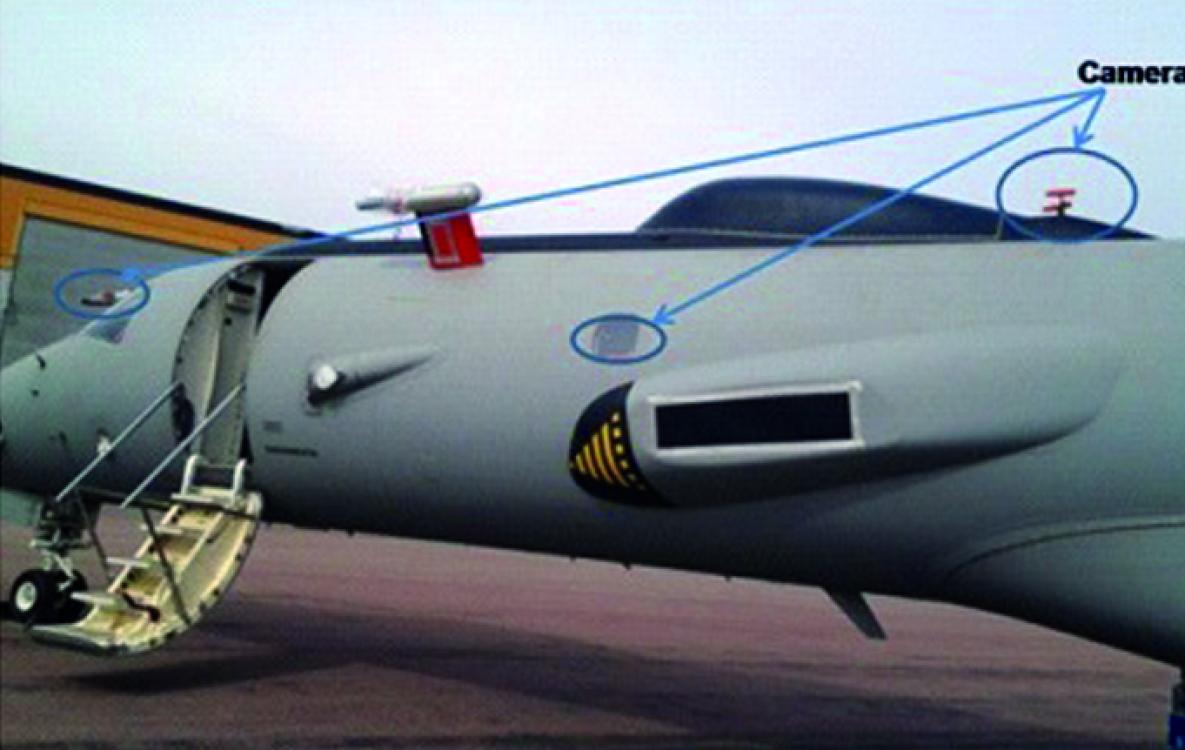
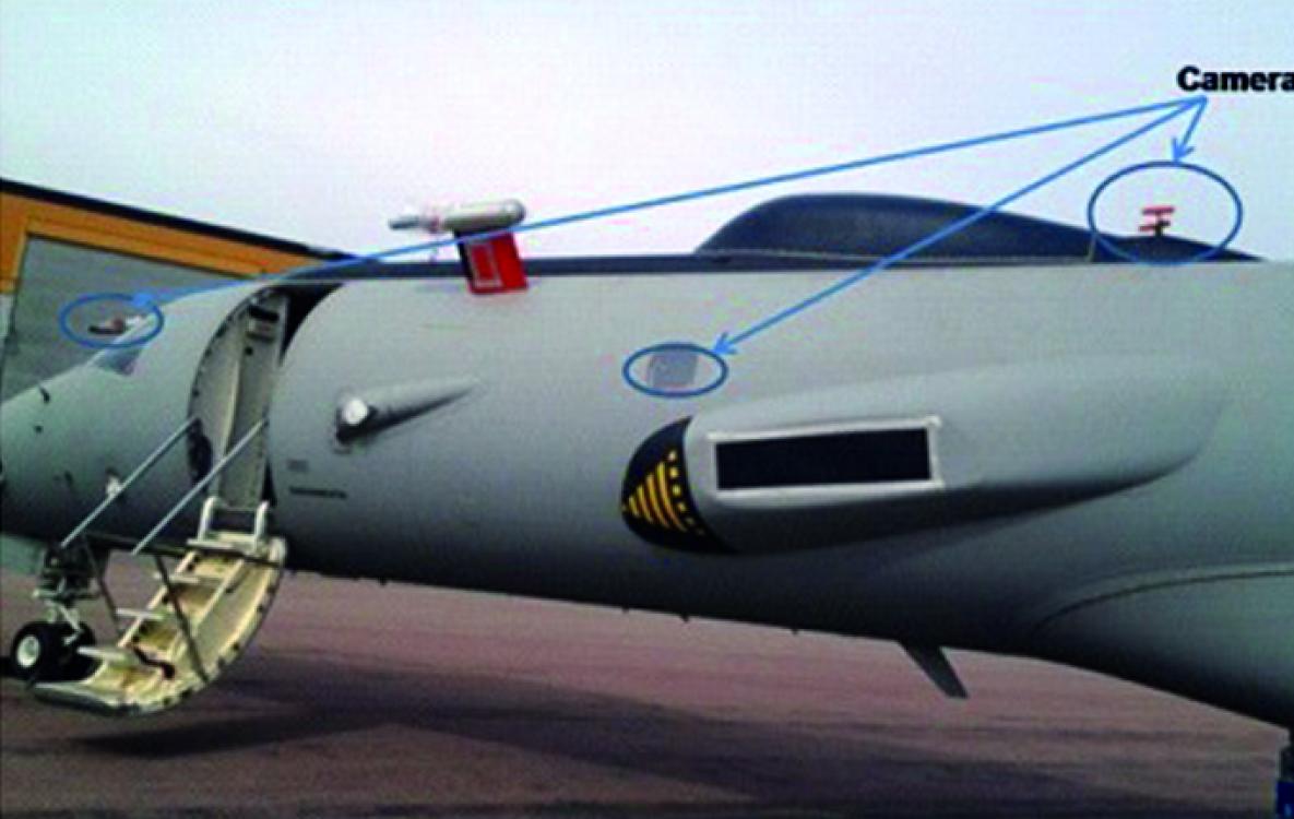
◊ Flight tests to demonstrate the aircraft performance in natural icing condition are carried out after literally ‘chasing’ the weather so as to get the desired natural icing conditions. The tests were executed after the ‘Right Clouds’ were found in Sweden and Norway. Additional instrumentation and external cameras were provisioned to facilitate these flight tests under natural icing conditions.
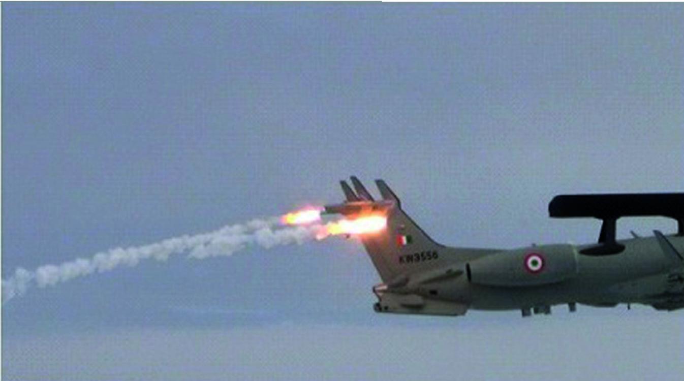
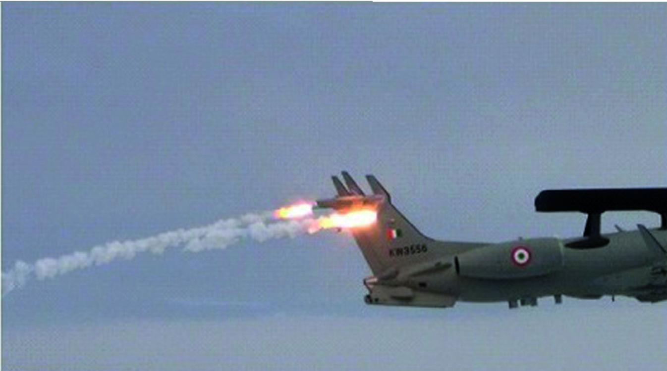
While the majority of the aircraft systems were certified in Brazil, same of the features were to be flight tested in India, CMDS safe separation trials. either due to the system peculiarities or owing to the availability of test infrastructure to execute the planned tests. The tests related to aircraft performance carried out in India were witnessed by CEMILAC to accord the requisite certification. The major flight tests of aircraft carried out on Indian soil are as follows:
CMDS Safe Separation Trials
Hot and high performance trials to evaluate the performance of the aircraft at higher temperatures and altitudes.
Mission System Flight Tests
The flight test of mission systems was carried out in India and executed by the joint team of flight test crew from CABS, DRDO and ASTE. There are several ‘Firsts’ during the developmental flight test activities of AEW&C mission systems. These flight tests of AEW&C mission systems lasted for over 06 years. The flight testing of AEW&C in India was jointly executed by a combined team comprising of designers and flight test crew from DRDO and IAF. The different types of sorties and their breakup is as follows:
• Mission : 750 hours & 64%
• Training : 143 hours & 12%
• Ferry : 186 hours & 16%
• Air Test/Handling/Shakedown:78 hours & 7 %
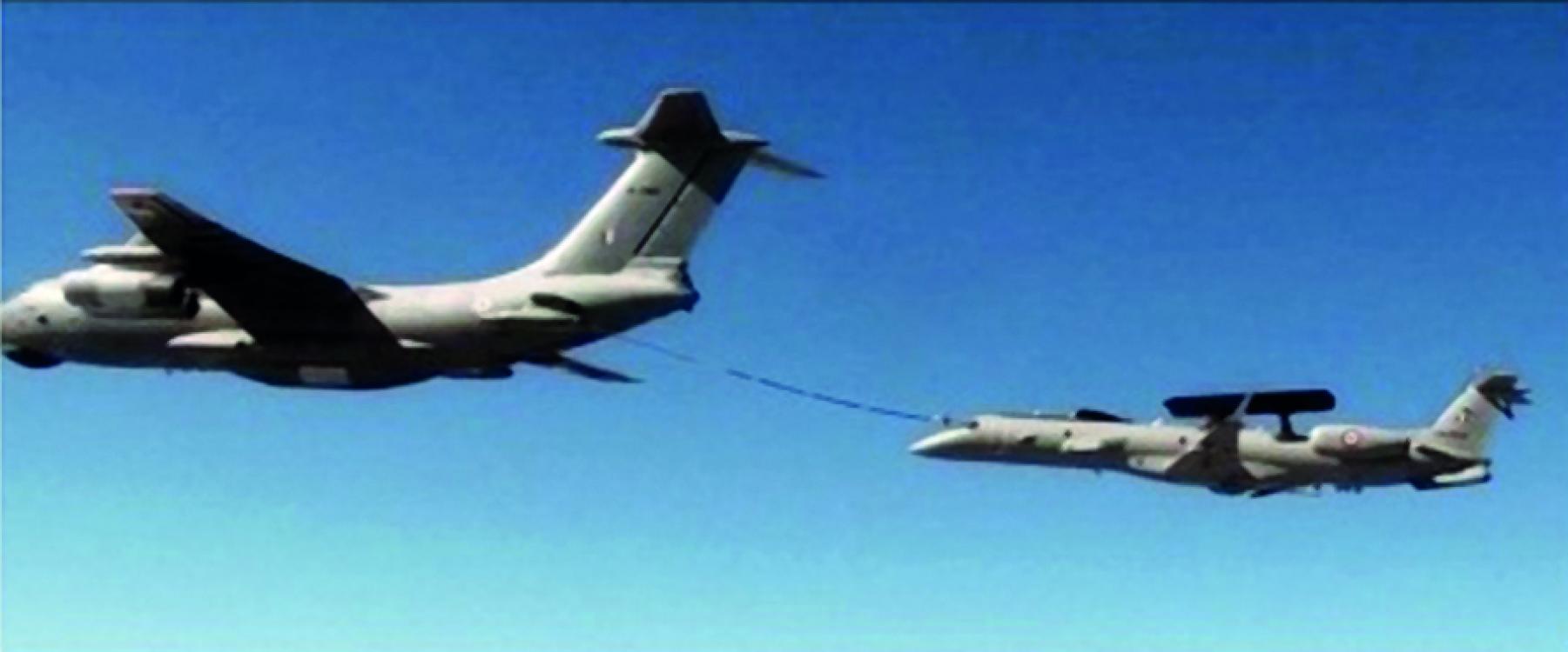
• AAR : 9 hours & 1%
The amount of effort that has gone into developing and testing the mission systems is very obvious from the above results. In addition, significant amount of training has been undergone by pilots of the IAF. The ferry sorties are an indicator, of the amount flight test campaigns that have taken place at various IAF bases. AAR or Air-to-Air Refueling sorties have been done successfully for the first time in India on a transport class of aircraft. Majority of the tests of mission system have been carried at Bangalore. However, the system performance in varying terrain conditions have been demonstrated by flying over thick forests in North East, valleys in the North, the desert regions in the West and the plateau conditions of the south.
◊ In addition, the performance of the mission systems has been extensively validated during several IAF exercises including Ex-Akraman. Participation and evaluation of mission system in Ex-Akraman provided an ideal platform to evaluate the active and passive sensors in a holistic way. The capability of the system has been dedicatedly tested while handling large force engagements and such trials provided an opportunity to understand the strengths and shortcomings. This has gone a long way in optimally refining the system to the satisfaction of the user.
Uniqueness of AEW&C Flight Tests
The AEW&C flight tests are unique and distinctive from the traditional flight testing of airborne systems. The salient features and acheivemnts of AEW&C flight tests are as follows:
◊ It has been for the first time in the country that such an extensive flight test of an airborne system has been carried out.
◊ The participation of designers and test crew from India during trials conducted in natural icing conditions was another ‘first’ for the country.
◊ The successful culmination of AEW&C flights tests has paved the way for operational induction of AEW&C, thereby enabling India to join a league of select nations with such a cutting-edge technology.
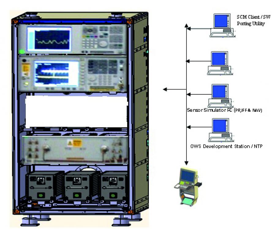
System Test Integration Rig
AEW&C System being a System of Systems poses greater challenges in integration. The integration gets challenging when these systems have to work in tandem to form an Integrated system. The complexity increases when the same is to function in an airborne environment where there are constraints in terms of volume, power, cooling etc.
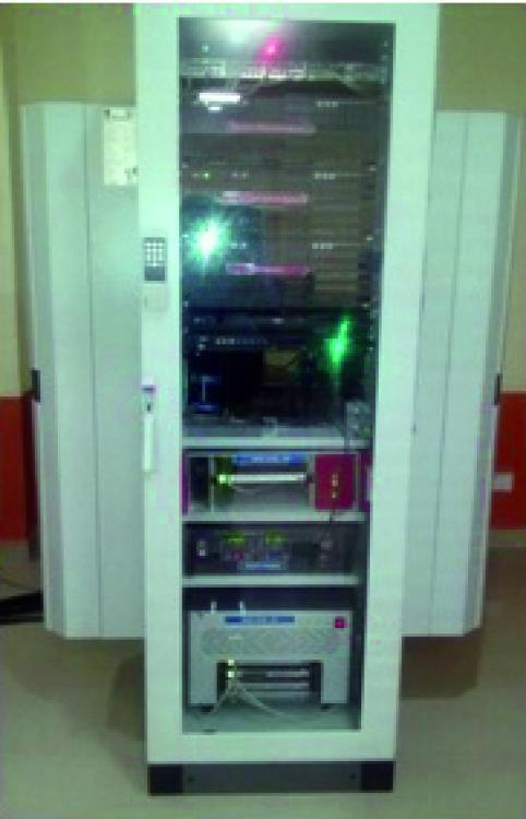
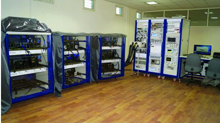
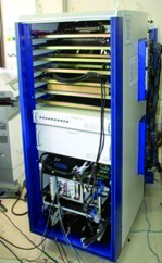
The System Test and Integration (STIR) facility ensures a smooth integration and necessary clearances from the stakeholders before being put on the aircraft to reduce both the time and costly flight testing of the systems. This facility is equipped with simulators for checking the system for mechanical, electrical, digital, RF and software integration and providing an integrated environment for tandem working of the system. The Rig also facilitates in terms of carrying out the behaviour of the systems under various scenarios that the mission is likely to encounter and caters for the stress testing of the system – especially when testing against 500 to 1000 targets, handling and ascertaining the lag in the systems for real time performances. The systems can be tested against the environments that are encountered in the operational situation ensuring the performances without subjecting resources in the forward areas for testing of the system.
The Mission Planning and Analysis Station (MIPAS) is a critical groundbased system which supports pre-and post-mission activities of the AEW&C.
The main task of MIPAS, at the pre-mission phase, is to prepare the Mission Parameter Data (MPD) Library to be uploaded to the AEW&C system. The uploaded MPD library serves as the technical and operational online database during the mission. The pre-mission phase outcome, which is the MPD library (a single MPD is for a specific, single mission sortie), consists of Pre Flight Messages (PFM) files and Tactical Mission Data (TMD) files. Each MPD consists of PFM for the subsystems, which include Radar, IFF, Mission Data Processor (MDP), CSM Communication Support Measures (CSM), Electronic Support Measures (ESM), Self-Protection Suite (SPS), Intercept Control Processor (ICP), Mission Recording and Playback (MRP), Operator Work Station (OWS), and Communication PFMs (V/UHF, CBand and SATCOM). TMD consists of Tactical Data Item (TDI), Weather Data, Mission Order, Mode Code Table, TYCO (Type and Configuration) and GRT (General Rule Table). Tactical Data Item include Fixed Points (like Airbases, Navigation aids, Radar sites, Surface to Air Missiles sites etc), Areas (like Defended areas, Danger zones, Flight corridors etc), and Flight Plans of known aircraft.
The PFM and TMD files are needed for the initialization and operation of the airborne mission systems in a specific mission scenario. In a mission sortie, AEW&C generates and records various sensor data (like ESM, CSM), voice, video, RT calls, and navigation data. All these recorded data are required to be decoded and analyzed to improve the performance in future missions. For each sortie these recorded data and video recordings of each operator consoles are very huge. These voluminous data needs to be analyzed in short time.
During post-mission, MIPAS supports data download, playback, analysis and report generation based on the downloaded data from the AEW&C. Facility to feed simulated data is also available.
The Ground Exploitation Station (GES) is a ground system that acts as an interface between the AEW &C and the IACCS. The real-time Recognizable Air Situation Picture (RASP) generated onboard AEW&C is transmitted to the GES, which is, interfaced with the IACCS through an interface unit for dissemination of tactical information to the decision makers on the ground. Similarly, the command from the IACCS to the AEW & C is routed through GES.
GES enables the officers to see, live, the sensor data collected by the onboard AEW&C sensors. All this visualization happens on ground (in GES)/Mission Control Room (in IACCS room).
The Communication between AEW&C and GES can happen in one of the three modes: CBDL Data link; Ku Band Data link; and V/UHF communication system.
The communication between GES and IACCS happens through Ethernet link. Once the sensors data is on IACCS network, it provides seamless availability of the information at any place across India. GES, being a modular design, is easy for transportation and deployment. Multiple GES can be operational at the same time and the live sensor data can be monitored at different geographical locations.
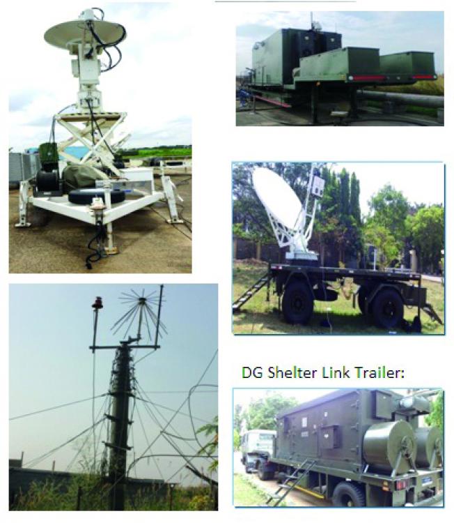
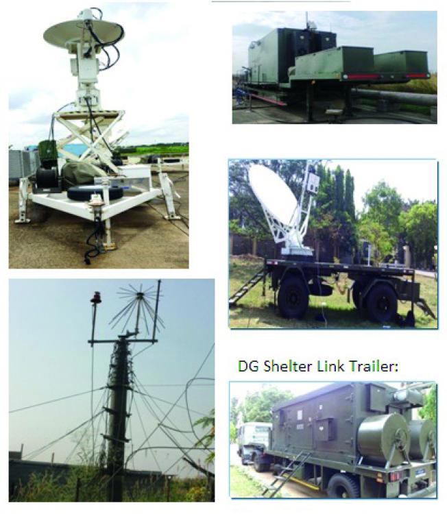
It comprises of mission system such as, Mission System Controller (MSC), Mission Communication System (MCS), C Band & Ku Band Data Link system and Operator Work Stations (OWS). All these systems are powered through a Diesel Generator (DG) system. As an entity it comprises of the following shelter / trailer based units, namely GES shelter, DG shelter, trailer mounted CBDL outdoor units, trailer mounted KBDL units and 18m VUHF antenna masts.
GES facility has been established at CABS as well as at Air Force Station Bhatinda, Air Force Station Jodhpur and Air Force Station Ambala. The main components of GES are as follows:
GES Operator shelter houses all the indoor LRUs of mission system. It has been designed to accommodate four racks (for fitment of LRUs, UPS and batteries) two operator work station consoles, one CCTV console and power distribution panel. Racks are fitted with various mission system LRUs like system controller, base band units, tracking receivers, antenna control unit, radios, high power amplifiers, VAIU etc.
C Band Data Link Trailer is fitted with a 1.8 meter dish antenna; with two feed (Main feed & Acquistion Aid Antenna). The antenna is fitted on a scissors lift, the scissors lift aids in the operation of the antenna at an elevated level. The CBDL trailer also houses a drive control unit, a RF system; a dehydrator and a scissors lift motor.
Ku Band Data link trailer is fitted with a 2.4 meter dish antenna; with its offset feed. The KBDL trailer houses a RF system consisting of Block Up Converter (BUC), Low Noise Block Down Converter (LNBC), and Electronic Compass. Four hydraulic jacks are provided for the trailers, which aids in meeting pointing accuracy of ground KBDL antenna towards satellite.
VUHF Masts two 18 meter masts are fitted near the shelter. VUHF antennas are fitted on top of these two masts, which help in attaining maximum range for communication. These are pneumatic masts which can be erected using air compressors.
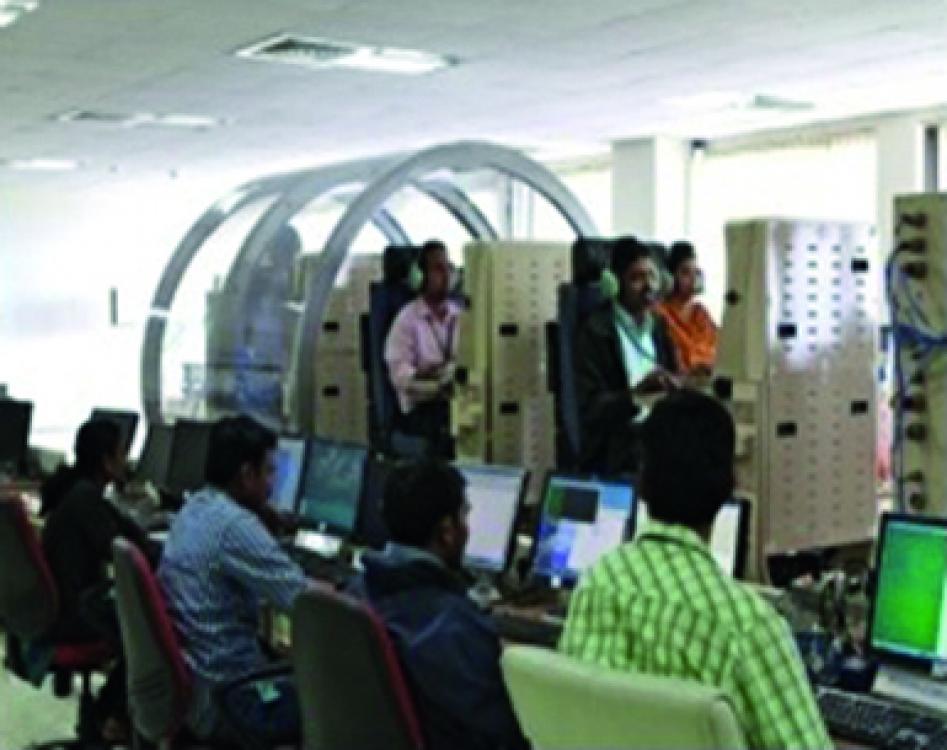
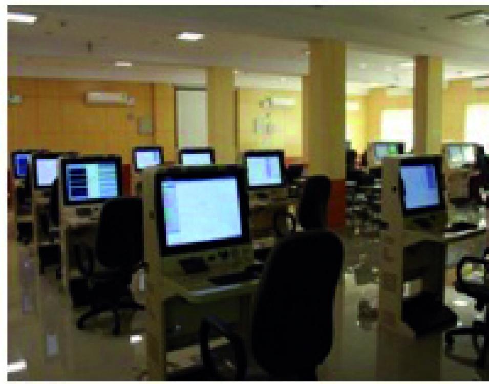
Operator Training Station (OTS) is a ground-based system for training the operators in a realistic, simulated environment for providing tactical training, command & control and battle management by simulating the behaviour of different airborne sensors under dynamically varying scenarios. It aids in providing hands on training to fighter controllers and judging the operational competence of the squadrons. It not only trains the operators in simulated scenarios comprising of Computer Generated Forces (CGF) but also by recreating previous mission sortie’s recorded large scale integrated exercise scenarios and thus providing exponential benefits. The facility enables enormous cost saving of training in flights of high value asset mission platforms such as AEW&C, thereby conserving precious flying missions.
This facility has been extensively used by the Fighter controllers/ Mission Operators for training under different battlefield scenarios on ground. The OTS has capability to train either five Mission operators with five instructors controlling each one of them or one Instructor, training nine mission operators simultaneously. It also has capability of simulated pilot sitting on IOS controlling its own simulated entities. OTS basically comprises of the Instructor Operator Station (IOS), Trainee Operator Station (TOS) and Server Rack.
The maintenance philosophy of the AEW&C system is maintenance at three levels, namely, I (Intermediate), O (Operational) and D (Depot). ‘O’ level maintenance tasks are performed at the operational base mostly in-situ for all the systems.
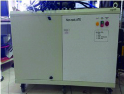
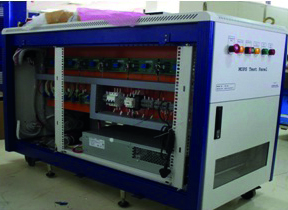
CABS has designed & developed Automated Test Equipment for testing of Mission System LRUs towards I level maintenance of AEW&C.
The purpose of the ATE is to provide the simulating input to the LRUs and measuring the response based on which decision can be made, whether LRU can be declared as OK or not. The testing of the faulty LRUs off loaded from the Mission System, is also done in ATE. It also carries out tests on spare LRUs to the required level of confidence prior to mounting into the Mission System. The ATE comprises modular and standard commercially-off-the-shelf test equipment interconnected through PXI/PXIe/GPIB bus and also through a fully managed Ethernet Switch. Excitation and measurement is done by the test equipment in the ATE through ITA.
The ATE software is built on industry standard platform- NI LabVIEW and NI Test Stand. NI Test Stand is ready-to-run test management software that is designed to develop automated test and validation. In addition, test sequences that integrate code modules written in any test programming language can also be developed. Sequences also specify execution flow, reporting, database logging, and connectivity to other enterprise systems.
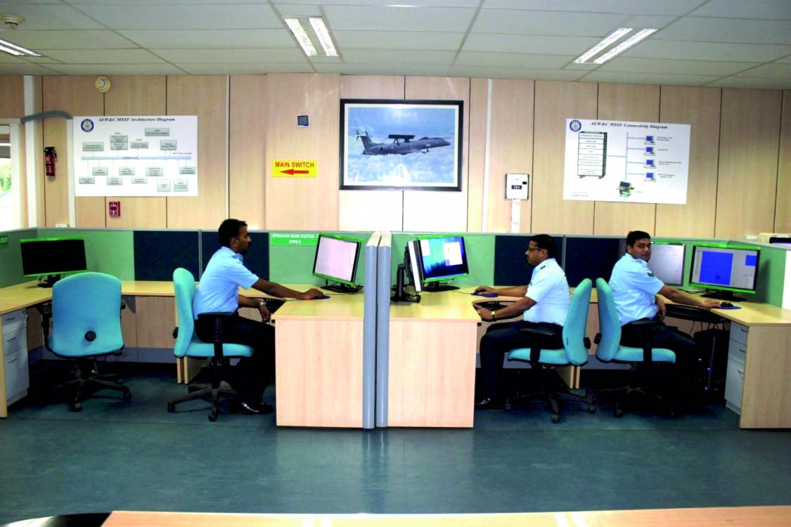
The Mission Software Support Facility (MSSF) is one of the Ground Segment of AEW&C & is used to provide software maintenance and configuration management of the AEW&C system. The AEW&C system software is maintained at CSCI (Computer Software Configuration Item) level in the MSSF facility. The MSSF is used as a secure and centralized repository to store the software work-products of AEW&C sub-systems.
The advantage of such repository is to make available all the software for AEW&C at a single place over the life time of the system. A Software Configuration Management server is used to store the software work-products.
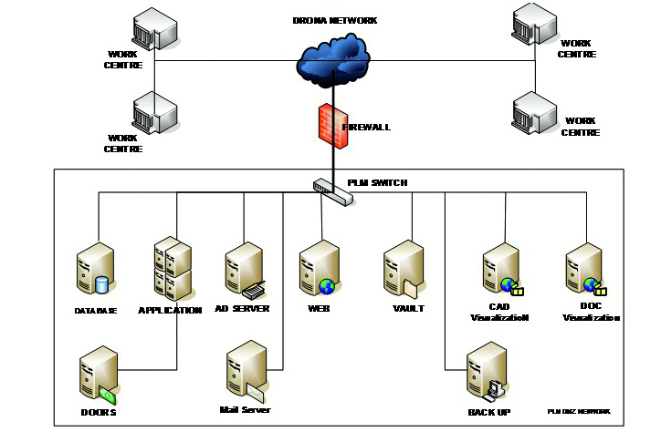
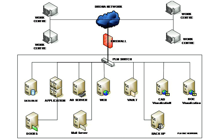
PLM as conceptualized for the AEW&C programme has been implemented as a new way to think about product information towards execution of DRDO programmes within the time & cost constraints meeting all the user specified requirements.
The design, development, integration & certification of the AEW&C system involves several partners geographically distributed. A need was felt to pull together interrelated and interdependent information and disparate applications into coherent processes and consolidate all the AEW&C Programme information & processes into a common system. It was felt necessary to provide a collaborative environment through deployment of state-of-the-art technologies both in hardware & software for managing the complex AEW&C Programme environment thereby enabling project teams to use tools, processes & methods that are unified under a heterogeneous environment.
The PLM solution proposed was about taking a ‘Systems Approach’ with respect to the information generated to support faster & more informed decision-making throughout the programme lifecycle. The system so implemented have the ability to capture data in a holistic manner with respect to the technology, processes and people across the organization as well as the work-centres working for the AEW&C development.
The software enabled an organized process for creation, updating, storage backup, archival, access control and retrieval of all data related with the AEW&C product & programme/ project. It also ensured the management and control of configuration for design data as well as to control the flow of work within and across work groups & workcentres in respect of product/ project data of the organization. It enabled in controlling processes and ensuring regulatory compliances. The document management and control functionalities built in to support all documentations of the organization including various types of design data such as drawings, 3D models, analysis, software outputs, in-house software, text documents etc. Data validation procedures ensured consistency & correctness of data. Thus, the PLM solution provided a complete enterprise solution for all its present and future endeavors in the development of the AEW&C Programme.
DESIDOC thanks Dr Reena Sharma, Sc ‘G’, Shri Y Maheshwaran, Sc ‘F’ of Centre For
Airborne Systems
(CABS) for bringing out this issue of Technology Focus
Editor-in-Chief: Dr Alka Suri
Assoc Editor-in-Chief: B. Nityanand
Managing Editor: Manoj Kumar
Editor: Dipti Arora
Editorial Assistance: Biak Tangpua, Raj Kumar
Printing: SK Gupta; Marketing: Tapesh Sinha
Local Correspondents
| Agra | Shri S.M. Jain, ADRDE |
|---|---|
| Ahmednagar | Col Atul Apte, Shri RA Shaikh, VRDE |
| Ambernath | Dr Susan Titus, NMRL |
| Bengaluru | Shri Satpal Singh Tomar, ADE |
| Smt M.R. Bhuvaneswari, CABS | |
| Smt Faheema A.G.J., CAIR | |
| Shri R. Kamalakannan, CEMILAC | |
| Ms Josephine Nirmala, DARE | |
| Shri Kiran G., GTRE | |
| Dr Sushant Chhatre, MTRDC | |
| Chandigarh | Shri Neeraj Srivastava, TBRL |
| Dr H.S. Gusain, SASE | |
| Chennai | Smt S Jayasudha, CVRDE |
| Dehradun | Shri Abhai Mishra, DEAL |
| Dr S.K. Mishra, IRDE | |
| Delhi | Shri Amit Pasi, CFEES |
| Dr Dipti Prasad, DIPAS | |
| Dr Nidhi Maheshwari, DIPR | |
| Shri Ram Prakash, DTRL | |
| Shri Navin Soni, INMAS | |
| Shri Anurag Pathak, ISSA | |
| Dr D.P. Ghai, LASTEC | |
| Ms Noopur Shrotriya, SAG | |
| Dr Rachna Thakur, SSPL | |
| Gwalior | Dr Manorama Vimal, DRDE |
| Haldwani | Dr Atul Grover, DIBER |
| Dr Ranjit Singh | |
| Hyderabad | Dr J.K. Rai, ANURAG |
| Shri A.R.C. Murthy, DLRL | |
| Dr Manoj Kumar Jain, DMRL | |
| Dr K Nageswara Rao, DRDL | |
| Jodhpur | Shri Ravindra Kumar, DL |
| Kanpur | Shri A.K. Singh, DMSRDE |
| Kochi | Smt Letha M.M., NPOL |
| Leh | Dr Tsering Stobden, DIHAR |
| Pune | Shri A.K. Pandey, ARDE |
| Dr J.A. Kanetkar | |
| Dr Himanshu Shekhar, HEMRL | |
| Dr Anoop Anand, R&DE(E) | |
| Tezpur | Dr Sibnarayan Datta |
| Dr Sonika Sharma, DRL |
Readers may send their suggestions to
The Editor, Technology Focus
DESIDOC, Metcalfe House
Delhi-110 054
Telephone: 011-23902403, 23902472;
Fax: 011-23819151; 011-23813465
E-mail: director@desidoc.drdo.in;
techfocus@desidoc.drdo.in;
technologyfocus@desidoc.deldom
Internet: https://www.drdo.gov.in/technology-focus


